| Basics of Coordinate Metrology Unit 6: Basics of Metrology - Real Geometry | Step 5 of 8 |
| After construction, the part is manufactured on the basis of the technical drawing. This is accompanied by deviations and deformations. They can be caused by the manufacturing machine, the external temperature, material defects and many other effects. The geometric elements of the manufactured part along with the deviations are called actual shape or real geometric elements. |  Real geometry of the part with manufacture- related deviations | ||||||||||||||||||||||||
In addition to the dimensional tolerances, the design engineer can also enter other tolerances in the drawing:
| List of the form and position tolerance symbols according to DIN ISO 1101: | ||||||||||||||||||||||||
| Form
| Position
| ||||||||||||||||||||||||
 | |||||||||||||||||||||||||
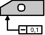
 Form tolerances serve for checking the dimensional deviation, in the above example for checking the straightness of all lines of the bottom area lying in parallel to the drawing plane.